Tuesday, June 21, 2016

Using a Flex Sensor

A flex sensor produces a resistance based on how much it is bent. This project used a Sparkfun flex sensor and a few LED's to test the functionality of the sensor.

A flex sensor has numerous functionality, especially for gesture control of various electronics as the video below shows.


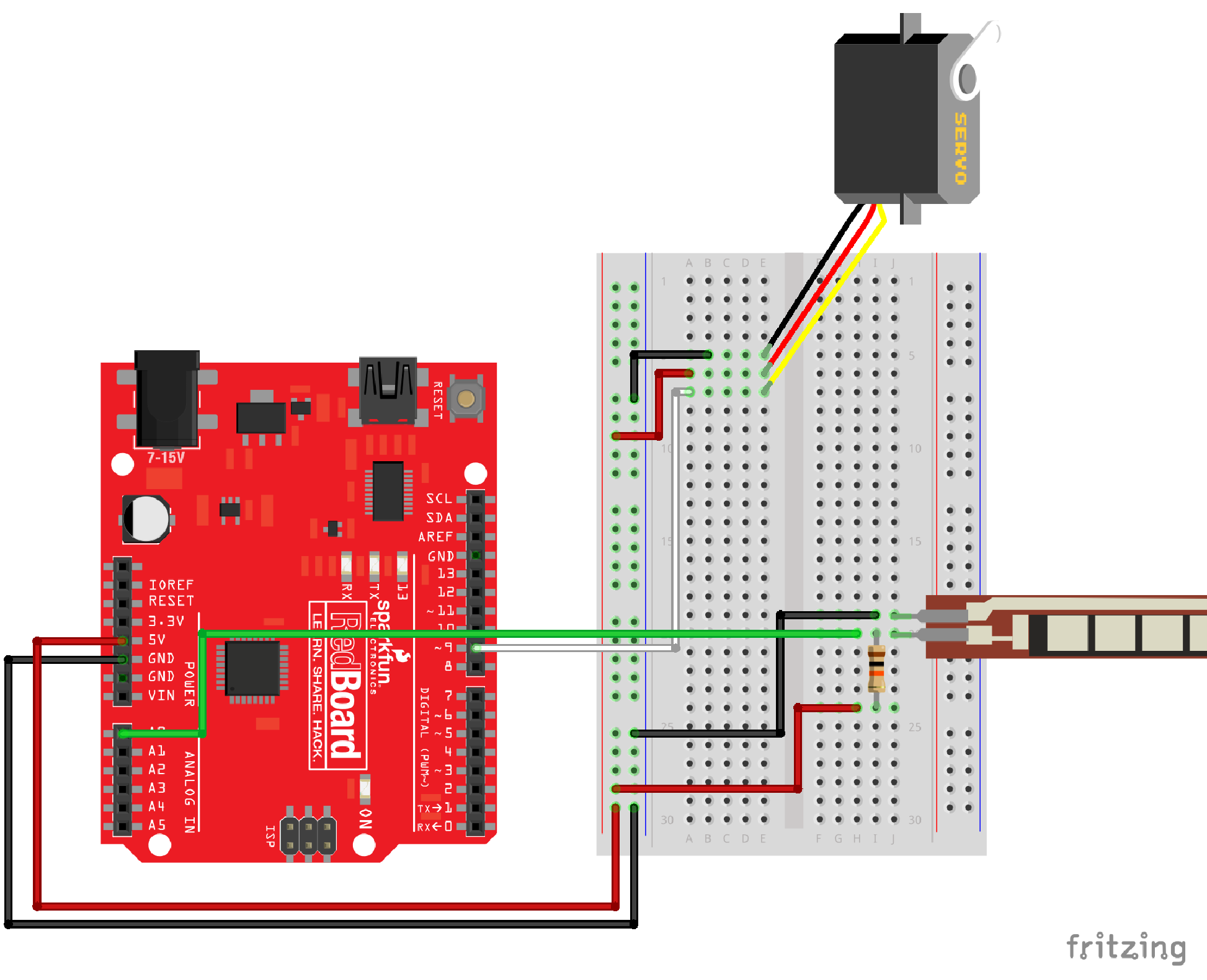
The diagram below from Sparkfun shows how to wire a flex sesnsor through a 10K voltage divider (the resistor). The servo can be ignored for the example below. 

https://cdn.sparkfun.com/assets/learn_tutorials/3/1/0/RedBoard_circuit_09_02-01.png

The video below shows the flex sensor in action. The number of LED's that go on is relative to how much the sensor is being bent.


  Here is the code:

int flexpin = 0;
int ledPins [] = {4,5,6,7};

void setup() {
  Serial.begin(9600);
 
  for (int i = 4; i < 8; i++) {
    pinMode(i, OUTPUT);
  }
  pinMode(13,OUTPUT);

}

void loop() {
  //digitalWrite(7,HIGH);

  int flexposition;


  flexposition = analogRead(flexpin);
  int  rate = map (flexposition, 780, 950, 0, 2000);
  rate = constrain (rate, 0, 2000);

  int intensity = map (rate, 0, 2000, 0, 4);
  //Serial.println(intensity);

  if (intensity > 0) {
    for (int i=0; i < intensity; i++) {
      digitalWrite(ledPins[i], HIGH);
  
    }  
  }

 
  if (digitalRead(ledPins[intensity]) == HIGH) {
    Serial.println(intensity);
    digitalWrite(ledPins[intensity],LOW);
  }

}


  //The code below does the same thing without using the last if statement. This is a less efficient
  //way of accomplishing the same thing.
 
  /*if (intensity < 4 && digitalRead (ledPins [3]) == HIGH) {
    digitalWrite (ledPins [3], LOW);
  }

  if (intensity < 3 && digitalRead (ledPins [2]) == HIGH) {
    digitalWrite (ledPins [2], LOW);
  }

    if (intensity < 2 && digitalRead (ledPins [1]) == HIGH) {
    digitalWrite (ledPins [1], LOW);
  }

    if (intensity < 1 && digitalRead (ledPins [0]) == HIGH) {
    digitalWrite (ledPins [0], LOW);
  }
//delay(100);

}*/

Tuesday, May 24, 2016

Pololu Trex Jr. Motor Controller - A breif Arduino hookup guide

Goal: Hookup a Pololu Tre Jr. Motor controller to an Arduino and get things (motors) moving.

The Trex Jr. Motor controller is versatile in the sense that it allows you to define easily which pins to use to receive and send commands. The Trex Jr. relies on sending byes of data back and forth between the arduino and the controller via the physical serial port of the arduino and a software serial port of the Trex Jr.

To hook it up, you will use the TTL (SI and SO pins) of the Trex jr. (most likely). The SI pin is the recieve pin of the controller and is connected to the pin that is defined as RX on the arduino (pin 5 in my example code). The SO is the transmit pin and it gets connected to the TX pin of the arduino (pin 4 in my example). Also the grounds need to be connected between the controllers.

Trex Jr. pin connection


SI ->TX (Arduino pin 4) and SO -> RX (Arduino pin 5)


Code: 
//Pololu Trex Jr.
#include SoftwareSerial.h //add <> around software serial.h
 #define TXPIN 4
#define RXPIN 5

SoftwareSerial pololu(RXPIN, TXPIN);

void setup() {
  pinMode(RXPIN, INPUT);
  pinMode(TXPIN, OUTPUT);
 
  Serial.begin(9600);
  pololu.begin(19200); //Trex jr. Serial port

 }

void loop() {

pololu.write(0xC2); //Send byte to target motor 1 forwards
pololu.write(127); Set motor 1 speed


pololu.write(0xC9); //Send byte to target motor 2 forwards
pololu.write(127); Set motor 2 speed


}

The command documentation for the Trex Jr. can be found here.


Saturday, April 30, 2016

Simple LED control with Xbee/Arduino and Processing

Goal: Turn a single LED on/off wirelessly though an Xbee chip connected to an Arduino using the control P5 library for Processing.

Materials: 
-LED
-330 Ohm resistor
-Xbee (2)
-Xbee shield for arduino
-Power Supply (4 AA battery holder)
-Arduino Uno

Assumption: 
-The Xbee is set up and configured
-The LED is connected to pin 13

Processing code:

//Turn on LED with button press using controlP5

import controlP5.*;
import processing.serial.*;

ControlP5 cp5;
Serial myPort;        // The serial port
int c2;

void setup() {
 
 // List all the available serial ports
 // if using Processing 2.1 or later, use Serial.printArray()
 println(Serial.list());

 // I know that the first port in the serial list on my mac
 // is always my  Arduino, so I open Serial.list()[0].
 // Open whatever port is the one you're using.
 myPort = new Serial(this, Serial.list()[0], 9600); 

 // don't generate a serialEvent() unless you get a newline character:
 myPort.bufferUntil('\n');
 
  size(400,600);
  noStroke();
  cp5 = new ControlP5(this);
 
 
   cp5.addButton("on")
     .setValue(0)
     .setPosition(100,100)
     .setSize(200,19)
     ;


  cp5.addButton("off")
     .setValue(100)
     .setPosition(100,120)
     .setSize(200,19)
     ;
        
}

void draw() {
  background(c2);
 

}

public void on(int theValue) {


   //if we clicked in the window
   myPort.write('1');         //send a 1
   println("1");  

}

public void off(int theValue) {
   myPort.write('0');         //send a 1
   println("0"); 

  c2 = color(#2408A5);
}


Arduino Code: 

#include  

char val;

SoftwareSerial XBee(2, 3); // Arduino RX, TX (XBee Dout, Din)

void setup() {
  //Serial Port begin
  Serial.begin (9600);
  XBee.begin(9600);
  pinMode(13,OUTPUT);
}

void loop()
{

  digitalWrite(13,HIGH);

   if (XBee.available())
   { // If data is available to read,
     val = XBee.read(); // read it and store it in val
   }
   if (val == '1')
   { // If 1 was received
     digitalWrite(13, HIGH); // turn the LED on
   } else {
     digitalWrite(13, LOW); // otherwise turn it off
   }
   delay(10); // Wait 10 milliseconds for next reading


How it works:
The button class of control P5 is activated on a button release event. When the button that says "on" is released, a value of '1' is written to the serial port that the XBee is connected to using the command myPort.write('value').

The Xbee (connected to the arduino) waits for data to become available (   if (XBee.available()) )and when the data is available , it reads the value (as a char value of "1" or "0" - if (val == '1') { ) and either turns and LED off or on.

Extending it:
The next step is to use a slider or a knob to send analog values to the arduino. The eventual goal is to be able to use sliders and dials to drive a robot while precisely controlling speed and turning radius. \

Monday, March 28, 2016

Sending and recieving commands from the Pololu Trex Jr. Motor Contoller

The more I try to do with 3d printing + robotics + arduino, the more I realize what a capable little microcontroller the Trex Jr. from Pololu is.

One of the big challenges that I faced when I first started messing around with the controller is sending and receiving command bytes to and from the controller using the Arduino. The following very simple code sends a command from the arduino to the motoe controller to turn one motor at full speed.

The code also receives information about the current draw from the controller and prints it to the serial monitor. As it says in the Trex jr. documentation, you need multiple the current received by 40 to get how much milliamps the motor is drawing.

#include

#define TXPIN 4
#define RXPIN 5

SoftwareSerial pololu(RXPIN, TXPIN);
int incomingByte = 0;

void setup() {
  pinMode(RXPIN, INPUT);
  pinMode(TXPIN, OUTPUT);
 
  Serial.begin(9600);
  pololu.begin(19200);

}

void loop() {

pololu.write(0xC2);
pololu.write(127);
pololu.write(0x8D);

          if (pololu.available()<68 br="">        
                // read the incoming byte:
                incomingByte = pololu.read();
                delay(2);              
               Serial.println(incomingByte);
             }
 
}